Email Us

Process Optimization

Inspection Optimization in SMT Manufacturing – A System-Level Engineering Guide

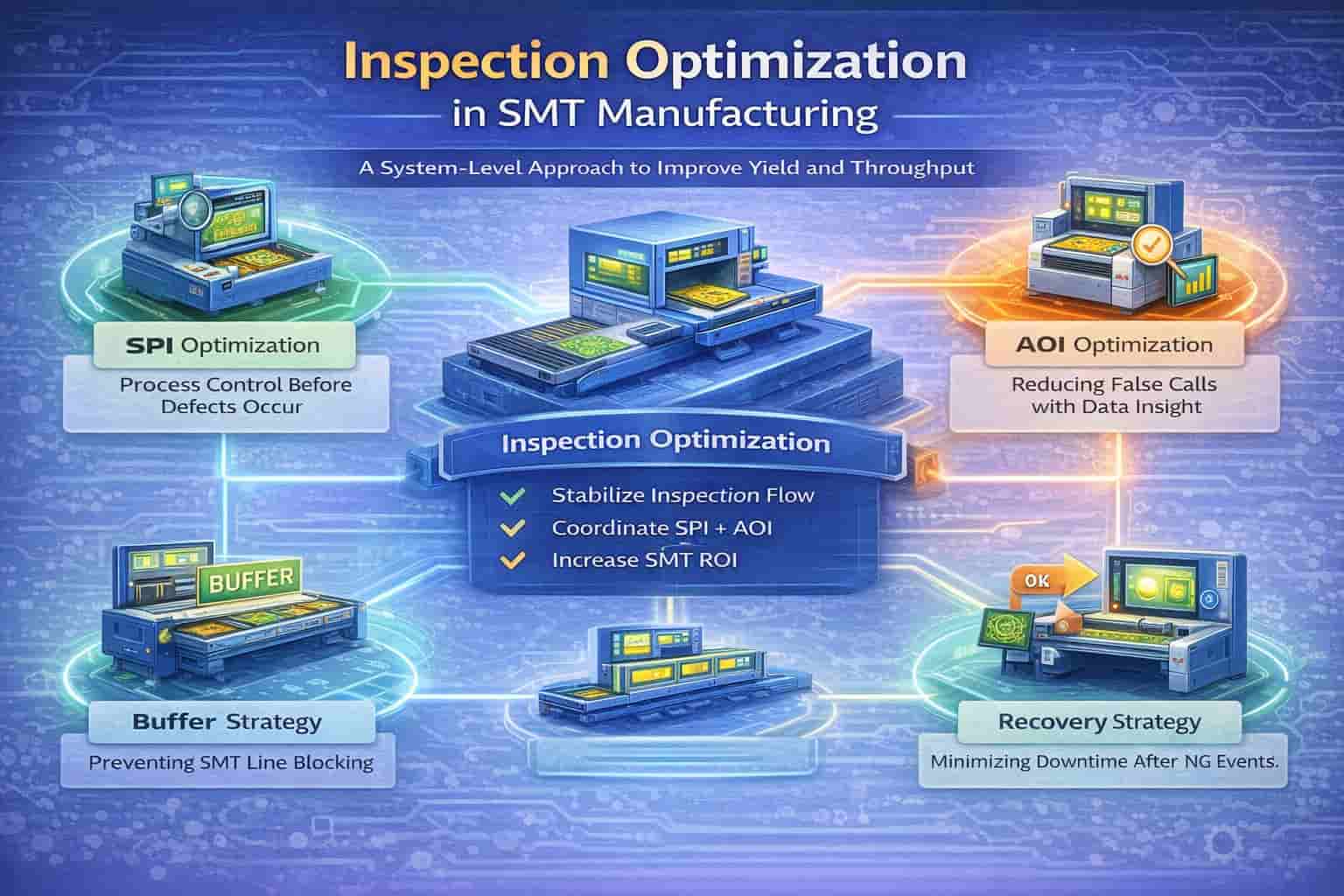
Inspection optimization is no longer about tuning a single SPI or AOI machine.
In modern SMT manufacturing, inspection is a system—closely linked to printing stability, placement accuracy, buffering strategy, recovery flow, and production economics.

Poorly optimized inspection leads to:

  • Excessive false calls

  • SMT line blocking and bottlenecks

  • Low first-pass yield (FPY)

  • High labor dependency and hidden cost

This Inspection Optimization Pillar Page provides a complete, system-level engineering framework covering SPI, AOI, data-driven optimization, buffering, recovery, and ROI impact.


Download
  • Product Details
  • Parameter
  • Video

1. What Is Inspection Optimization in SMT?

Inspection optimization is the process of balancing defect detection, inspection accuracy, and production flow, rather than maximizing inspection strictness.

True inspection optimization focuses on:

  • Detecting real quality risks early

  • Avoiding unnecessary inspection stops

  • Protecting line throughput

  • Supporting engineering decision-making

Inspection should support production, not dominate it.


2. The Role of SPI and AOI in the Inspection System

SPI – Process Control Tool

SPI is best used for:

  • Solder paste volume and height monitoring

  • Trend analysis and early warning

  • Printing process stability assessment

SPI should control the process, not reject boards for cosmetic variation.


AOI – Assembly Verification Tool

AOI excels at:

  • Component presence and polarity

  • Placement accuracy

  • Solder joint appearance after reflow

AOI should verify results, not duplicate SPI’s responsibility.


3. The Most Common Inspection Optimization Mistake

The biggest mistake is optimizing SPI and AOI independently.

This leads to:

  • Overlapping inspection responsibility

  • Excessive AOI false calls

  • Inspection cycle time inflation

  • SMT line blocking

Inspection optimization must be coordinated.


4. Defining a Clear SPI–AOI Inspection Boundary

A mature inspection strategy assigns responsibility deliberately:

Inspection ItemSPIAOI
Solder volume & height✅ Primary🔁 Trend reference
Paste alignment✅ Primary🔁 Confirmation
Component presence✅ Primary
Polarity✅ Primary
Solder joint wetting🔁 Trend✅ Primary

Clear boundaries reduce conflict and false calls.


5. AOI False Call Optimization – Core Principles

False calls are not random—they are system signals.

Root causes usually include:

  • Over-aggressive AOI thresholds

  • Poor golden board strategy

  • Optical artifacts

  • Upstream process variation

Optimization focuses on reducing noise without hiding risk.


6. SPI Data-Driven AOI Adjustment (Core Method)

SPI provides upstream context that AOI lacks.

Key SPI metrics for AOI adjustment:

  • Volume distribution

  • Height variation

  • Cp / Cpk

  • Pad-level consistency

Data-Driven Logic

  • Stable SPI → Relax AOI solder rules

  • SPI drift → Maintain or tighten AOI

  • High variation → Fix printing, not AOI

This approach drastically reduces false calls.


7. Inspection Flow and Buffering Strategy

Even optimized inspection generates:

  • Variation in cycle time

  • Occasional NG boards

Buffers are required to:

  • Absorb inspection fluctuation

  • Protect upstream placement

  • Enable recovery without blocking

Inspection and buffering must be designed together.


8. Recovery Strategy – The Hidden Performance Factor

Inspection recovery includes:

  • NG board routing

  • Manual review

  • Restart procedures

Poor recovery design causes more downtime than inspection itself.

Best practices:

  • Clear NG logic

  • Offline review when possible

  • Standardized operator actions


9. Inline vs Offline Inspection Strategy

Inline Inspection

Best for:

  • High-volume, stable products

  • Mature inspection programs

Offline Inspection

Better for:

  • High-mix production

  • Engineering validation

  • False-call-heavy processes

Hybrid inspection strategies often deliver the best ROI.


10. Inspection Optimization KPIs

Track optimization success using:

  • AOI false call rate

  • Inspection cycle time

  • Recovery time

  • SMT line blocking incidents

  • First-pass yield (FPY)

Metrics must improve together—not in isolation.


11. ROI Impact of Inspection Optimization

Poor inspection optimization leads to:

  • Lost throughput

  • Excess labor cost

  • Underutilized equipment

Optimized inspection:

  • Increases effective capacity

  • Improves ROI without new machines

  • Reduces operational stress

Inspection optimization is often the highest ROI improvement project in SMT.


12. When to Revisit Inspection Strategy

Re-optimize inspection when:

  • Product mix changes

  • New solder paste or components introduced

  • False calls increase

  • Line blocking becomes frequent

Inspection optimization is a continuous engineering process.


Conclusion

Inspection optimization is not about loosening limits or buying better machines.
It is about system thinking—aligning SPI, AOI, buffering, recovery, and production goals.

When inspection is optimized correctly:

  • Quality improves

  • Throughput stabilizes

  • ROI increases

This is the foundation of mature SMT manufacturing.


Linking Suggested Reading


Thomao Engineering Insight

Inspection should guide production decisions,
not interrupt production flow.


CONTACT US
Welcome your presence, you can send us an email, we will get in touch with you within 24 hours.
Room 502, Building 3H, Quanzhi Technology Industrial Park, Bao'an District, Shenzhen, China
sales@thomao.com
0086-176 0765 6429