Email Us

Process Optimization

SPI vs AOI Optimization – A Joint Strategy for Stable SMT Quality and Throughpu

SPI and AOI are often treated as independent inspection stations in SMT production.
In reality, SPI and AOI form a tightly coupled quality system—and optimizing one without considering the other often leads to false calls, inspection bottlenecks, and unstable production flow.

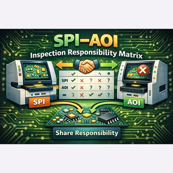
This article presents a joint SPI + AOI optimization strategy, explaining how to allocate inspection responsibility, tune parameters collaboratively, and improve both yield and line stability.


Download
  • Product Details
  • Parameter
  • Video

1. Understanding the Different Roles of SPI and AOI

Before optimization, it is critical to understand what SPI and AOI are best at detecting.

SPI excels at:

  • Solder paste volume and height

  • Insufficient or excessive paste

  • Printing alignment issues

  • Early process deviation detection

AOI excels at:

  • Component presence and polarity

  • Placement offset and rotation

  • Solder joint shape and wetting

  • Post-reflow assembly defects

Optimizing both systems to detect the same issues leads to redundancy and instability.


2. The Common Mistake: Overlapping Inspection Responsibility

A frequent optimization error is:

  • SPI checking too many cosmetic details

  • AOI over-analyzing solder defects already controlled by SPI

This overlap increases:

  • Inspection time

  • False calls

  • Operator review workload

Effective optimization starts with clear inspection responsibility separation.


3. Define a Clear SPI–AOI Inspection Boundary

A joint strategy assigns responsibility deliberately:

Inspection ItemPrimary OwnerSecondary Role
Solder volume / heightSPIAOI trend check
Paste alignmentSPIAOI confirmation
Component presenceAOI
PolarityAOI
Solder joint shapeAOISPI trend reference
Process driftSPIAOI feedback

Clear boundaries reduce conflict between inspection systems.


4. Use SPI as a Process Control Tool, Not a Defect Gate

SPI should focus on:

  • Trend monitoring

  • Early warning of printing drift

  • Process stability indicators

Avoid using SPI as a hard pass/fail gate for cosmetic variation, which creates unnecessary NG boards.


5. Optimize AOI Based on SPI Feedback

SPI data can be used to:

  • Dynamically adjust AOI tolerance

  • Identify areas where AOI false calls can be relaxed

  • Detect real process drift vs normal variation

AOI should react intelligently to SPI trends, not operate blindly.


6. Reduce AOI False Calls Through SPI-Aware Programming

If SPI confirms stable paste conditions:

  • Relax AOI solder joint thresholds

  • Reduce false calls caused by acceptable variation

  • Focus AOI resources on placement-related defects

This coordination significantly improves AOI throughput.


7. Align SPI and AOI Cycle Time with Line Takt

Joint optimization must consider takt time:

  • SPI too slow → early bottleneck

  • AOI too strict → downstream blocking

Balancing both inspection speeds prevents accumulation and line stoppage.


8. Plan Recovery and Review Flow Together

SPI and AOI recovery logic should be aligned:

  • Clear rules for when boards stop the line

  • Defined escalation paths

  • Offline review for ambiguous cases

A shared recovery strategy reduces confusion and downtime.


9. Inline vs Offline Strategy in Joint Optimization

Inline SPI + AOI works best when:

  • Product mix is stable

  • Inspection programs are mature

Offline or hybrid strategies are better when:

  • False call rates are high

  • Engineering validation is ongoing

  • Line stability is at risk

Joint optimization includes choosing the right inspection mode.


10. KPIs to Monitor in SPI–AOI Joint Optimization

Key indicators include:

  • SPI trend deviation rate

  • AOI false call rate

  • Combined inspection cycle time

  • Line blocking incidents

  • First-pass yield (FPY)

Tracking both systems together reveals real improvement.


Conclusion

SPI and AOI should not compete—they should collaborate.

A joint optimization strategy:

  • Reduces false calls

  • Improves inspection efficiency

  • Stabilizes SMT line flow

  • Increases overall yield and ROI

True inspection optimization happens at the system level, not machine by machine.


Linking Suggested reading:


Thomao Engineering Insight

SPI controls the process.
AOI protects the result.
Optimization connects both.


CONTACT US
Welcome your presence, you can send us an email, we will get in touch with you within 24 hours.
Room 502, Building 3H, Quanzhi Technology Industrial Park, Bao'an District, Shenzhen, China
sales@thomao.com
0086-176 0765 6429